Final layout
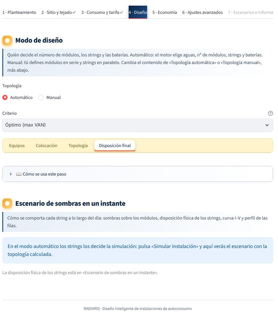
The 4 · Design → Final layout tab shows how the installation has turned out. It is filled in when you simulate: until then you will only see the structure.
3D scene
Read-only scene with all the roof planes and the placed modules. The plane chosen in the selector is highlighted. Choose a day and time to see the shadows cast by objects, neighbouring buildings and rows.
String I-V curves
Next to the scene you can see how shading affects each string at that moment: curve with and without shading, maximum power point and loss. With Full screen you see everything at once. If the curve has several maxima (marked), a tracker that stays on a local one would deliver less power than shown, which is the global maximum.
Physical layout
Plan and sections of each plane with the placed modules: number of rows and columns, row spacing, tilt, edge margin and position of the obstacles.
What to check before delivering
- That no module sits on a chimney or skylight.
- That the edge margin meets what the roof regulations or your own criteria require.
- That the most shaded modules are in separate strings (or have optimizers).
- That the number of modules matches the offer.
Export
The scene can be exported to DXF or OBJ to take it into your CAD program: see Library, Cadastre and CAD.