3D roof editor
The roof is modelled as a set of planes: each plane is a rectangular roof section with its own tilt and azimuth. A mono-pitch roof has one; a gable roof, two; a hip roof, four; and building volumes at different heights can be combined.
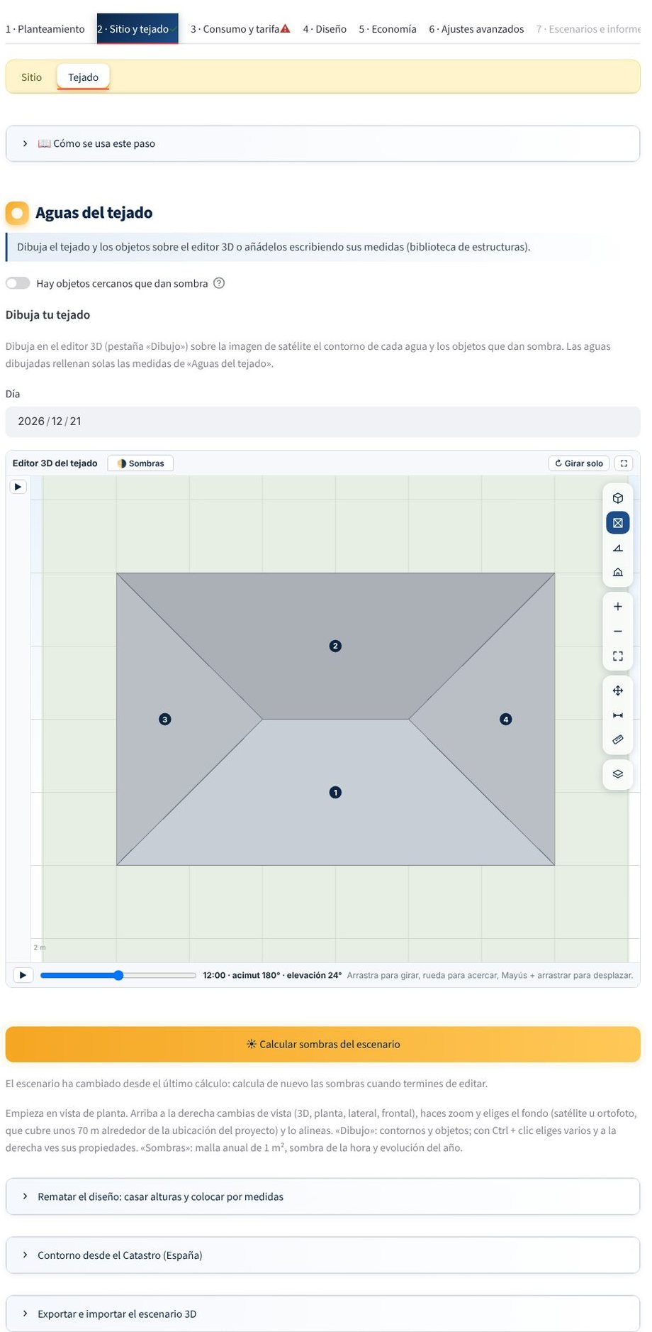
Drawing on the satellite image
In the Roof tab of step 2:
- Trace the outline of each plane (polygon) on the satellite image.
- The tilt and azimuth are filled in on the «Roof planes» cards; you can correct them. Azimuth convention: 0° = north, 90° = east, 180° = south, 270° = west.
- Enter the eaves height (height above the ground) if the building has several volumes: it is used to calculate the shading between planes.
The drawings are saved with the project. Conversions to metres are always made relative to the site, so moving the site does not change the relative geometry.
Planes
Each plane has:
| Data | Description |
|---|---|
| Name | It appears in the topology and in the report |
| Outline | Real drawn polygon, with the usable area calculated |
| Tilt | Angle of the roof relative to the horizontal |
| Azimuth | The direction the plane faces |
| Eaves height | Height of the lower edge above the ground |
The orientation of the modules can differ from that of the roof (for example, modules raised on a flat roof). It is configured in Module placement and does not overwrite the physical roof.
Objects that cast shade
Enable «There are nearby objects that cast shade» and draw chimneys, machines, skylights, trees, poles, walls or neighbouring buildings with their height. See Objects and shading model.
3D view
The editor shows the scene in 3D with planes, walls and objects. After simulating, in 4 · Design → Final layout you will see the placed modules and the shading at the time and day you choose (Final layout).
Modules are not drawn here
In the editor you only define the roof and the obstacles. The engine places the modules according to the outline, the margins and the shading.